If you’re looking for wiring diagrams and color codes for Pioneer car stereos you’ve come to the right place. All the info we’re using is from manuals which can be found at Pioneer’s official site. Although most of the Pioneer car stereos are using the same wiring diagrams, we advise you to find the original manual specifically for your model so you can be sure you’re using the correct info.
In this article, we’re gonna explain wiring diagrams for certain car radios including double din Pioneer DMH-100BT and FH-X720BT, and single din Pioneer MVH-S21BT.
Table of Contents
Pioneer MVH-S21BT (Single DIN)
16-pin wiring diagrams & color codes
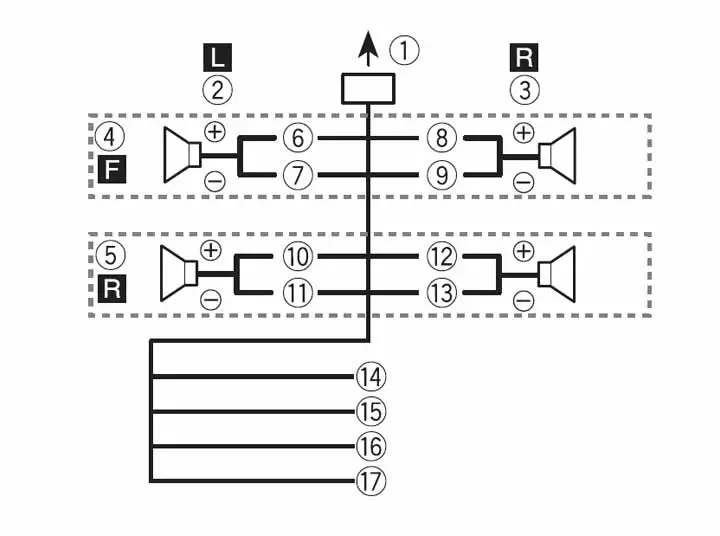
When connecting the rear and front speakers.

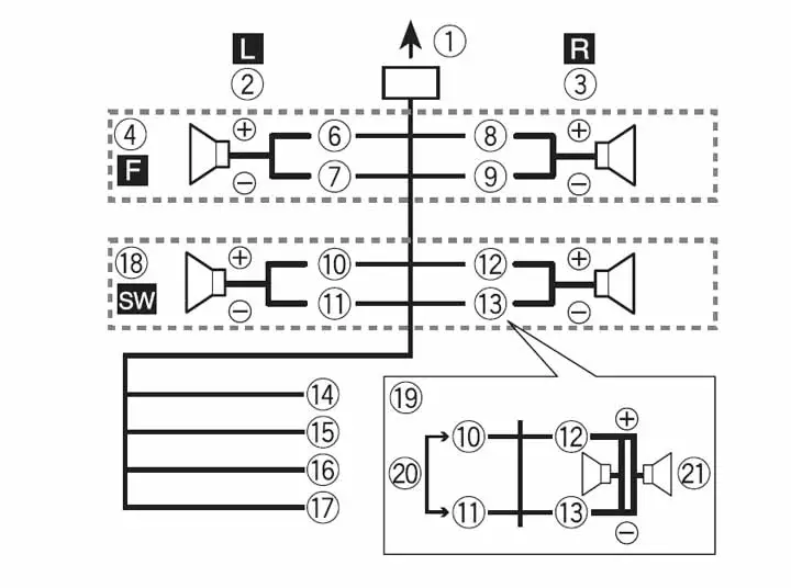
Connecting a subwoofer without the additional amplifier.
6. – 7. – Left front speaker: White (+), White/black (-)
8. – 9. – Right front speaker: Gray (+), Gray/black (-)
10. – 11. – Left rear speaker (left): Green (+), Green/black (-)
12. – 13. – Right rear speaker (right): Violet (+), Violet/black(-)
14. Black (chassis ground) – Connect to a clean, paint-free metal
location.
15. Yellow – Connect to the constant 12 V supply
terminal.
16. Red – Connect to the terminal controlled by the
ignition switch (12 V DC).
17. Blue/white – Connect to the system control terminal
of the power amp or auto-antenna relay
control terminal (max. 300 mA 12 V DC).
18. Subwoofer (4 Ω)
19. When using a subwoofer of 2 Ω,
be sure to connect the subwoofer to the
violet and violet/black leads of this unit. *Do not connect anything to the green
and green/black leads.
20. not used
21. Subwoofer (4 Ω) × 2
When using the optional amplifier.
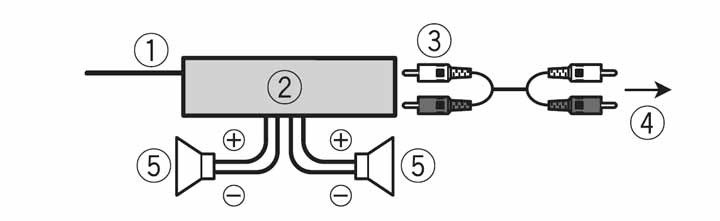
- System remote control
- Connect to blue/white cable.
- Power amp (sold separately)
- Connect with RCA cables (sold
separately) - To rear output or subwoofer output
Rear speaker or subwoofer
Connections
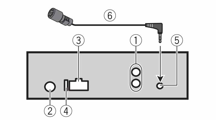
- Rear output or subwoofer output
- Antenna input
- Power cord input
- Fuse (10 A)
- Microphone input
- Microphone 3 m (9 ft. 10-1/8 in.)
All info is taken from the manual.
Pioneer DMH-100BT (Double DIN)
Power cord
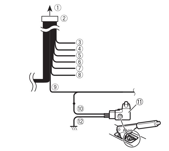
- To power supply
- Power cord
- Yellow – power
- Red – ignition switch (12 V DC) ON/OFF
- Orange/white – lighting switch
- Black (ground) – to vehicle (metal) body.
- Violet/white – Of the two lead wires connected to the back lamp, connect the one in which the voltage changes when the gear shift is in the REVERSE (R) position. This connection enables the unit to sense whether the car is moving forward or backward.
- Blue/white – Connect to the system control terminal of the power amp (max. 300 mA 12 V DC).
- Light green – ON/OFF status of the parking brake. This lead must be connected to the power supply side of the parking brake switch.
- Power supply side
- Parking brake switch
- Ground side
Speaker wiring
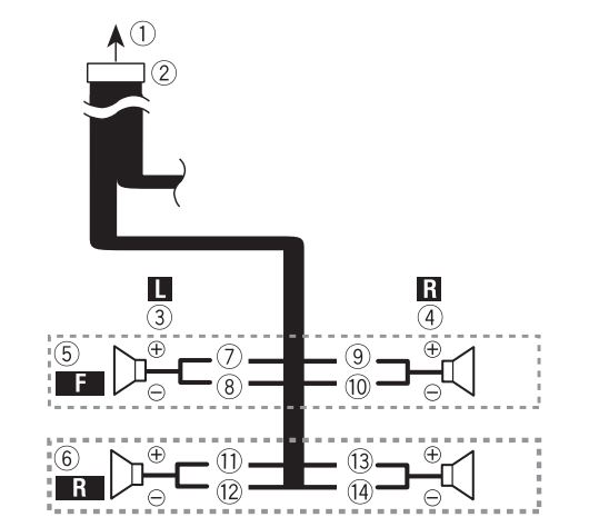
- To power supply
- Power cord
- Left
- Right
- Front speaker
- Rear speaker
- White
- White/Black
- Gray
- Gray/black
- Green
- Green/black
- Violet
- Violet/black
- Pioneer FH-X720BT (Double DIN)
All info is taken from the DMH-100BT manual.
Pioneer FH-X720BT (Double DIN)
14-pin wiring diagrams & color codes
The wiring when connecting a rear and front speaker.
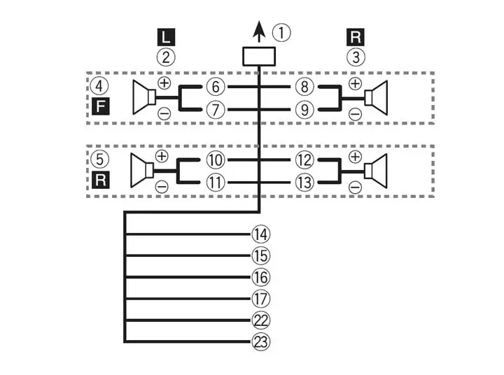
Diagram when using a subwoofer with front speakers.
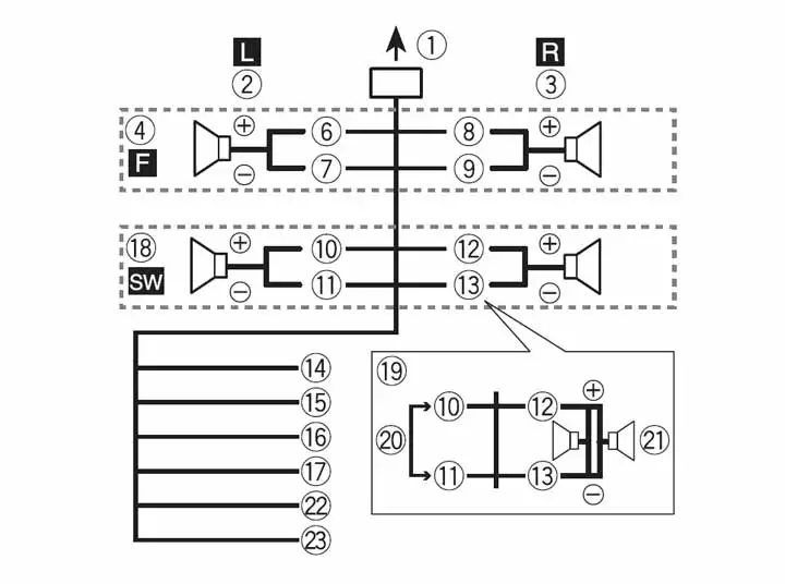
6. – 7. – Left front speaker: White (+), White/black (-)
8. – 9. – Right front speaker: Gray (+), Gray/black (-)
10. – 11. – Left rear speaker (left): Green (+), Green/black (-)
12. – 13. – Right rear speaker (right): Violet (+), Violet/black(-)
14. Black (chassis ground) – Connect to a clean, paint-free metal
location.
15. Yellow – Connect to the constant 12 V supply
terminal.
16. Red – Connect to the terminal controlled by the
ignition switch (12 V DC).
17. Blue/white – Connect to the system control terminal
of the power amp or auto-antenna relay
control terminal (max. 300 mA 12 V DC).
18. Subwoofer (4 Ω)
19. When using a subwoofer of 2 Ω,
be sure to connect the subwoofer to the
violet and violet/black leads of this unit. *Do not connect anything to the green
and green/black leads.
20. not used
21. Subwoofer (4 Ω) × 2
22. Orange/white – Connect to a car’s illumination wire.
23. Yellow/black (Only for FH-X520UI) – If you use equipment with a Mute function, wire this leads to the Audio Mute lead on that equipment. If not, keep the Audio Mute lead free of any connections.
When connecting to an amplifier.
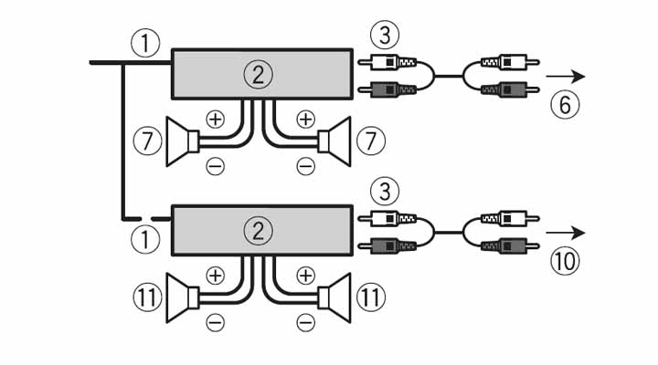
- System remote control
Connect to blue/white cable. - Power amp (sold separately)
- Connect with RCA cables (sold
separately) - To rear output
- Rear speaker
- To front output
- Front speaker
- To subwoofer output
- Subwoofer
- To rear output or subwoofer output
- Rear speaker or subwoofer
Connections

- Power cord input
- Microphone input
- Microphone (4 m)
- Rear output or subwoofer output
- Front output
- Antenna input
- Fuse (10 A)
- Wired remote input – Hard-wired remote control adapter can
be connected (sold separately).
All info is taken from the Pioneer FH-X720BT manual.